This chapter covers:
-
The evaluation of a specific global tiling scheme for CDB X,
-
The configurable grouping of Levels of Detail to balance file size versus file count,
-
An approach to packaging one or more data layers in GeoPackages (including coverage, vector and 3D data),
-
Current and proposed GeoPackage extensions for storing this data, and
-
The results of related prototyping activities.
The tiling sub-group was initially assigned specifically to explore tiled coverage data However, based on initial work, some experiments evolved beyond the initial testing scope. The additional experimentation applied the same tiling approach to vector data and 3D models and used existing or new extensions to store this tiled data in GeoPackages.
A key particpant decision was what container technology would be used for the majority of the experiments in which tiled structures are required. For the purposes of experimentation coupled with a community and sponsor reqwuirements, OGC GeoPackage structured containers were determined to be the primary storage format for derived vector data layers, coverages, and other data types as identified (TBD). The two OGC GeoPackage Standards of relevance are OGC GeoPackage version 1.1 and OGC GeoPackage Extension for Tiled Gridded Coverage Data.
Further, based on the discussions and results of the experimentation, the Tiling Subgroup participants believe the following recommendation.
Recommendation: Any tiling schemes specified in a CDB X data store (repository) SHALL be based on and consistent with the:
Additional information is now provided on these key OGC standards that are highly relevant to the development and approval of CDB 2.0.
This OGC Abstract Specification consists of two Parts: A General Tiling Conceptual Model and, based on the Conceptual Model, a Logical Model for the Tessellation (Tiling) of 2D Euclidean Space. Tiling of 2D Euclidean space is the most commonly known approach to partitioning space in traditional geospatial technology. However, there are also common elements and/or semantics for any approach to partitioning space in any dimension. The logical model in this document defines a set common required elements and then follows with more specific requirements for the two dimensional case.
Part 1 of the Abstract Specification describes a general tiling conceptual model. The conceptual model is applicable to any dimension. The conceptual model makes no assumptions regarding content, use cases, implementation scenarios, or how the space is to be tessellated (tiled). The conceptual model is abstract and cannot be implemented as is.
Part 2 of the Tiling Abstract Specification defines a detailed logical model for the tessellation of 2D Euclidean Space. One or more logical models are required to provide the requirements and structure necessary for implementation. Therefore, in addition to the conceptual model, this Abstract Specification also specifies a core logical model for the 2D planar (Euclidean) use case.
The OGC Tile Matrix Set standard defines the rules and requirements for a tile matrix set as a way to index space based on a set of regular grids defining a domain (tile matrix) for a limited list of scales in a Coordinate Reference System (CRS) as defined in [OGC 08-015r2] Abstract Specification Topic 2: Spatial Referencing by Coordinates. Each tile matrix is divided into regular tiles. In a tile matrix set, a tile can be univocally identified by a tile column a tile row and a tile matrix identifier. This document presents a data structure defining the properties of the tile matrix set in both UML diagrams and in tabular form. This document also presents a data structure to define a subset of a tile matrix set called tile matrix set limits. XML and JSON encodings are suggested both for tile matrix sets and tile matrix set limits. Finally, the document offers practical examples of tile matrix sets both for common global projections and for specific regions.
The following are the design principles for a CDB X tiling, levels of detail, and layering. These design principals were discussed and documented during Phase 1 discussions as well as during the experimentation. Again, for the purposes of expediting experimentation, GeoPackage was the choice for a standard container.
-
Use metadata for whole datasets that describe how data layers are regrouped (LOD grouping and data layer grouping).
-
Provide for fewer top level tiles than in OGC CDB 1.x.
-
Store imagery in a container according to the tiling scheme specified below.
-
Store coverage data in the container according to the tiling scheme specified below (
need anchor). Suggested coverage types based on current CDB standard and user specified requirements: (Ellipsoidal body surface): Elevation models, visual and non-visual (multi-spectral) imagery, terrain light maps (emissive at night), and raster materials (for non-visual sensors). Should be extensible to support other types. -
Coordinate Reference System is WGS 84 with epoch encoding (same as current CDB Standard except for epoch).
-
Need to keep the various encodings that CDB 1.x already has:
-
Elevation compression encodings (use of scaled integers vs floating point for smaller data sizes).
-
Elevation grids that are adjustable (better terrain fidelity at lower LODs/zoom levels)
-
Raster Material encodings using multiple coverage layers.
-
Imagery Compression (Imagery is typically the largest layer in CDB by disk storage).
-
-
Must enable a "relatively" easy migration path from the CDB 1.1/1.2 tiling/LoD structure into the CDB X structure.
The following figure, based on the Tiling Abstract Specification Logical Model and the CDB 1.x Conceptual Model, shows the properties by class (concept) and the relationships between the classes.


The proposed tiling scheme would be based on the GNOSISGlobalGrid, where the tiling starts with a 2x4 grid of tiles with each tile 90 degrees on a side that covers the whole Earth. This is zoom level 0 (or tile matrix identifier "0"). The experiments performed during the sprint used the tile size of 256 x 256 defined by the GNOSIS Global Grid for all zoom levels / level of details. A variation of the Tile Matrix Set definition using a different tile size instead, e.g. 512 x 512 could also be experimented it. At each successive zoom level, each lower level tile is split into four new tiles at the next zoom level The exception that any tile that touches either the North or South Pole is not split in the longitude direction. This subdivision can continue until the zoom level is high enough to accommodate the highest resolution data that is to be stored within the CDB X.
References for the GNOSISGlobalGrid tiling scheme:
-
OGC Standard Tracker - Global WGS84 tiling scheme adapted to polar regions (quad tree except for always having 4 tiles at the poles)
-
OGC Ideas Repository - Global tiling grid approximating equal-area while maintaining a simple latitude/longitude aligned rectangular tile layout (not quite a DGGS).

The following graph compares the CDB 1.x zones with the Gnosis grid and shows how the GNOSIS algorithm helps to keep the typical tile closer to a “square” than CDB’s zones.

|
Note
|
A summary of all of the results from the experiments can be found in Annex B. |
Benefits from changing to the proposed tiling scheme:
-
OGC CDB 1.x has 41,220 top level tiles. This requires opening huge numbers of files to visualize the Earth at global scales. The proposed CDB X tiling would use 8 tiles to cover the Earth at the coarsest level of detail.
-
The concept of "zones" in OGC CDB 1.x are still present in the tiling scheme, but algorithmically derived rather than at fixed latitudes. New zones are introduced at higher levels of detail, keeping the tiles near the poles closer to an ideal square shape than in OGC CDB 1.x
-
The ratio of the longitude size of tiles is always 1:1, 2:1, or the inverse 1:2, where OGC CDB 1.x has several ratios that must be supported, such as 2:1, 3:2 and 4:3.
Drawbacks to changing from the CDB 1.x approach to the proposed tiling scheme include the following. NOTE: These issues would require some level of rework for existing CDB applications to be compatible with the new tiling scheme.
-
The new tiling scheme is incompatible with OGC CDB 1.x, as there is no alignment between the tile areas and the LOD or zoom levels. To convert data between these two tiling schemes would require merging and splitting of raster data tiles, while changing their resolution, and would require reprocessing all the coverage data (like imagery).
-
Some CDB applications might have more trouble with tiles that are not based on integer latitude and longitude boundaries.
-
Some CDB applications might have an issue with a format where there are not a fixed number of "zones" (using the OGC CDB 1.x term) or different grid cell sizes used. This is because the GNOSIS grid introduces a new "zone" closer to the poles at each successive zoom level to help preserve a grid cell that is closer to an ideal square real world size.
-
Tile Matrix Set naming (numbering) is different from OGC CDB 1.x, with the numbering starting from the top left corner of a set of tiles in CDB X versus starting from the bottom left corner of a set of tiles in OGC CDB 1.x.
The coverage, vector and 3D models data could be stored using GeoPackage containers. Imagery and coverage data would always be tiled. Vector data could optionally be stored in tiles using extensions for tiled vector data being standardized in the OGC. 3D models could either be stored in a single table referenced by placement points, or as batched tiled 3D models.
There are two proposed ways to group data within a series of GeoPackage containers. Within these choices is a tradeoff between the format simplicity of working with a single container, and access latency due to larger file and table sizes.
-
For users at the edge and smaller areas, the Subgroup particpants
recommendthat all the CDB X coverage layers be present within a single GeoPackage container. This approach could be result from an export from a larger CDB X dataset, where only the resolutions and the boundaries of the data needed are stored and delivered to an end user. Users at the edge are such individuals as field operatives using mobile devices with limited battery, memory, storage and processing capabilities as well as Delayed/Disconnected, Intermittently-connected or Limited bandwidth (DDIL) environments. -
For Modeling and Simulation uses, as well as data repository cases, the Subgroup participants
recommendthat a series of GeoPackage containers be used to store CDB X coverage layers. This involves storing a region of the world at a set of zoom levels, or levels of detail, within a single GeoPackage, with a specified file and directory naming scheme. This approach would allow for faster access to data at specified areas and zoom levels. This approach would also lend itself to concurrent access and editing for data repository maintainers.-
The particpants propose that a configurable grouping value be used to specify how many zoom levels or levels of detail are put into a single GeoPackage. This would be a tradeoff between the number of GeoPackages created and the file and table sizes within each GeoPackage.
-
Multiple grouping numbers were experimented with. Five (5) was found to be a good number for packaging together all data layers of the San Diego CDB. For these experiments, a number of datasets were used, including CDB 1.x data from both the Presagis Sample CDB of Camp Pendleton, as well as the San Diego sample CDB provided by CAE. Additional data from NASA Visible Earth Blue Marble and USGS GTOPO30 were used to test applying the tiling to global datasets. This grouping number might need to be adjusted for different types of data layers, or different data sets as well.
-
The proposed naming of each GeoPackage file is based on the layer name and the coarsest, lowest level tile included within the grouping inside the GeoPackage. That tile’s level, row (from the top) and column within the tile matrix set make up the filename, along with the level of the finest or highest level tile that can be placed into this GeoPackage. For example: Coverages_L4_R16_C12_L6.gpkg
-
The proposed directory naming creates a directory tree that limits the number of GeoPackage files that could exist within a single directory. Each GeoPackage would exist within a set of directory names that represents each coarser or lower zoom level GeoPackage that encompases the smaller higher resolution area. For example: The file, Coverages_L4_R16_C12_L6.gpkg, would exist in the directory named Coverages\L0_R1_C0\L1_R2_C1
-
The file and directory naming needs to be easy to compute algorithmically or exist within a catalog, without having to search a data repository to discover arbitrarily named files.
-
-
To facilitate extraction from a large (or even worldwide) dataset and easily merge these extracted sub-datasets as well as the ability to augment these base datasets with additional more detailed insets, without repackaging the entire dataset, the following solutions are proposed:
-
The publisher of a large repository of data could pre-establish fixed maximum LODs for specific data layers (e.g. imagery, elevation, 3D Models).
-
When inset data is added to a dataset, these could go beyond the regular maximum LOD specified for the 'packaging'. As such these inset tiles are always grouped together with the tiles of the regular maximum LOD.
Recommendation: Define this capability for splitting GeoPackages based on a specific tiling scheme outside of the CDB X standard so that this split content can be used by itself.
|
Note
|
A mechanism to split data and group (or not) layers over multiple GeoPackages by tiles / LOD grouping (or have it all as a single GeoPackage), as well as a JSON schema providing the necessary information to access that data (e.g. packages, data layers, grouping, maxLOD, selected TileMatrixSet), should be a modular standard defined outside of CDB X, so that it could be used for other large datasets not necessarily conforming to the CDB X standard (e.g. the OrdnanceSurvey Master Map, OpenStreetMap Planet OSM, etc.). |
The Tiling Subgroup developed a simple schema for describing the data layers provided in a CDB X datastore, which CDB component selector they correspond to, and how they are packaged in one or more packages. These packages can themselves either be stored in a single GeoPackage (zero or null LOD grouping), or separated in multiple GeoPackage based on tiles grouped in multiple LODs (non-zero LOD grouping). This index allows the flexibility to use the best suited configuration for a given dataset or use case At the same time it is very simple for a client to parse and access the data in a deterministic manner using any of these configurations.
When a single GeoPackage is used, potentially this cdb.json could be included inside as metadata (using the GeoPackage metadata extension) to make
this GeoPackage a single file, very portable compliant CDB X.
The following cdb.json index files demonstrate the three main configuration possibilities.
Additional examples are also provided along with the experiments results.
Example 1: Two data layers (with a maximum LOD of 16 and 18) packaged as a single GeoPackage ("groupLOD" : 0 — all LODs grouped together).
This would be a single file named SampleCDBX.gpkg.
{
   "packages" : [
      {
         "name" : "SampleCDBX",
         "tms" : "GNOSISGlobalGrid",
         "groupLOD" : 0,
         "maxLOD" : 18,
         "layers" : [
            {
               "name" : "Elevation",
               "cs1" : 1,
               "maxLOD" : 16
            },
            {
               "name" : "Imagery",
               "cs1" : 4,
               "maxLOD" : 18
            },
         ]
      }
   ]
}
Example 2: Two data layers (with a maximum LOD of 16 and 18) packaged as a single package, grouped in GeoPackages covering tiles across 5 LODs.
The one package would be organized in a folder named SampleCDBX, and the GeoPackages files will be grouped by 5 counting down from the maximum LOD 18,
e.g. SampleCDBX/L0_R0_C0/L4_R10_C11/L9_R324_C356/SampleCDBX_L14_R10376_C11415_L18.gpkg.
{
   "packages" : [
      {
         "name" : "SampleCDBX",
         "tms" : "GNOSISGlobalGrid",
         "groupLOD" : 5,
         "maxLOD" : 18,
         "layers" : [
            {
               "name" : "Elevation",
               "cs1" : 1,
               "maxLOD" : 16
            },
            {
               "name" : "Imagery",
               "cs1" : 4,
               "maxLOD" : 18
            }
         ]
      }
   ]
}
Example 3: Three data layers (with a maximum LOD of 16, 18 and 13) packaged as three separate packages.
Elevation is grouped in GeoPackages covering tiles across 6 LODs, Imagery is grouped in tiles across 7 LODs while Buildings are stored grouped in a single GeoPackage.
The Elevation package would be organized in a folder named Elevation, and the GeoPackages files would be grouped by 5 counting down from the maximum LOD 16,
e.g. Elevation/L0_R0_C0/L5_R20_C22/Elevation_L11_R1302_C1427_L16.gpkg.
The Imagery package would be organized in a folder named Imagery, and the GeoPackages files would be grouped by 7 counting down from the maximum LOD 18,
e.g. Imagery/L0_R0_C0/L5_R20_C22/Imagery_L12_R2605_C2855_L18.gpkg.
The Buildings would be stored in a single file named Buildings.gpkg.
{
   "packages" : [
      {
         "name" : "Elevation",
         "tms" : "GNOSISGlobalGrid",
         "groupLOD" : 6,
         "maxLOD" : 16,
         "layers" : [
            {
               "name" : "Elevation",
               "cs1" : 1,
               "maxLOD" : 16
            }
         ]
      },
      {
         "name" : "Imagery",
         "tms" : "GNOSISGlobalGrid",
         "groupLOD" : 7,
         "maxLOD" : 18,
         "layers" : [
            {
               "name" : "Imagery",
               "cs1" : 4,
               "maxLOD" : 18
            }
         ]
      },
      {
         "name" : "Buildings",
         "tms" : "GNOSISGlobalGrid",
         "groupLOD" : 0,
         "maxLOD" : 13,
         "layers" : [
            {
               "name" : "Buildings",
               "cs1" : 100,
               "cs2" : 1,
               "subComponent" : 1,
               "maxLOD" : 13
            }
         ]
      }
   ]
}Recommendation: Consider also defining this description of the packages and LOD grouping outside of the CDB X standard so that description can be used elsewhere as well.
The current OGC CDB tiling scheme can be described as a Tile Matrix Set (TMS) that encodes the CDB fixed zones and the larger tile dimensions, as seen in this example description (JSON encoding).
Using this TMS, a profile or extension of OGC CDB 1.x could be created that would support the same GeoPackage containers and level of detail groupings, while conforming to the OGC CDB 1.x conceptual model. Using this approach could bring in some concepts of CDB X into OGC CDB 1.x and make the transition easier to a future version of OGC CDB.
|
Note
|
We do not recommend supporting more than one tiling scheme in a version of CDB, as this choice is foundational to how data layers are processed and stored and accessed. |
The experiments completed in this effort made use of a proposed GeoPackage Tile Matrix Set extension defined and initially tested in the 2019 OGC Vector Tiles Pilot Phase 2, which enables support for the GNOSIS Global Grid. This extension has not yet been adopted as an official OGC GeoPackage extension, but is on the GeoPackage Standard Working Group (SWG) roadmap. The current draft is available from here: GeoPackage Two Dimensional Tile matrix Set (TMS) extension (Draft).
|
Note
|
Even though most current software do not yet support the GeoPackage TMS extension, the level 0 data (e.g. for the BlueMarble imagery sample GeoPackages) will still work e.g. in QGIS, as the GNOSIS Global Grid does not use variable widths at level 0. |
The GeoPackage Tiled Gridded Coverage extension would be ideal for storing tiled coverage data. However that Standard has drawbacks that need to be addressed.
Current limitations include:
-
Only single channel data is allowed in the coverage extension. Many CDB coverages use more than one channel (Imagery, Raster Materials, etc.). The alternative would be to store CDB X coverage data using different GeoPackage concepts, such as tiles for imagery, coverages for elevation, and related tables for raster material data.
-
Current change request: http://ogc.standardstracker.org/show_request.cgi?id=662
-
-
GeoTiff data only supports using 32-bit floating point data. In OGC CDB 1.x, GeoTiff files are used to store 8 bit unsigned and 8, 16, or 32 bit signed binary data as well. Therefore the proposed OGC CDB 1.2 will also adopt the use of binary 1-bit data elements as well.
-
Current change request: http://ogc.standardstracker.org/show_request.cgi?id=661
-
-
An issue was filed asking for better clarity about whether 16-bit PNG encoding is signed or unsigned
Multiple sample GeoPackages using TMS / GNOSISGlobalGrid are described and linked below in the results of the experiments.
The following are recommendations and suggested additional discussion topics. These recommendations and discussion topics resulted from the Tiling sub-groups discussion on an enhanced tiling model for CDB X and the potential impacts on the various data types (layers) in the current CDB standard and existing CDB data stores.
CDB X needs to continue supporting the Min/Max Elevation component concept. In order to reduce the number of files and complexity, the recommendation is to move the minimum and maximum elevation values for the gridded elevation coverage contained in a tile to the tile metadata.
|
Note
|
The MinElevation and MaxElevation components are part of the MinMaxElevation dataset whose purpose is to provide a CDB conformant data store with the necessary data and structure to achieve a high level of determinism in computing line-of-sight intersections with the terrain. The values of each component are with respect to WGS-84 reference ellipsoid. |
Recommendation: That loss-less and lossy image compression solutions be explored for use in CDB X. Any such solutions are not viewed as a replacement for JPEG 2000 but instead as alternatives. This could be accomplished by submitting a change request for the OGC GeoPackage standard that provides guidance and requirements for support of other image formats beyond PNG and JPG. The sub-group identified a potential candidate: FLIF - Free Lossless Image Format, although this format looks to be relatively slow as well.
|
Note
|
JPEG-2000 has very high compression, even in lossless mode, and there are multiple open-source implementations. However, performance can be extremely slow and non-optimal for all use cases. |
Recommendation: CDB X needs to support material data to provide the same functionality as CDB 1.x. To also reduce the number of files, this can be accomplished by putting all the raster material data (including material table) in a single CDB data layer in GeoPackage, perhaps using the related tables extension. The subgroup did have some discussion on what "materials" means in the CDB 1.x context. Materials in current CDB have to do with the physical substance of a feature that can then be used to simulate the emmisive or reflective properties of a feature in wavelengths of the electromagnetic spectrum other than what the human eye senses. These are for non-visualization use cases or special visualization such as IR or Radar. The subgroup did also discuss for the possible need for CDB X to provide guidance on using Physically-Based Rendering (PBR) to support the visualization/rendering use case. glTF, I3S, and 3D Tiles all support PBR.
To tile vector data (including points referencing 3D models), draft GeoPackage extensions defined during the OGC Vector Tiles pilots were used:
-
GeoPackage Vector Tiles The draft GeoPackage Tiled Vector Data extension defines the rules and requirements for encoding tiled feature data (aka "vector tiles") into a GeoPackage data store.
-
GeoPackage Vector Tiles Attributes Extension This draft extension defines a relationship between features contained in a tiled layer and tiles containing those features.
-
MapBox Vector Tiles extension The draft GeoPackage Mapbox Vector Tiles extension defines the rules and requirements for encoding vector tiles in a GeoPackage data store as Mapbox Vector Tiles.
As an alternative to encoding tiled vector data as Mapbox Vector Tiles, some experiments used the GNOSIS Map Tiles encoding, specified by Ecere in OGC Testbeds 13 and 14.
Recommendation: Although the use of non-tiled vector data layers (e.g. storing the geometry as WKB in GeoPackage features tables) should also be specified
in the CDB Standard, the use of tiled vector data extension should be allowed. In particular, tiling vector data is essential for dealing with features spanning
a very large geospatial extent, such as coastlines (e.g. OpenStreetMap ways tagged with natural=coastline).
|
Note
|
Tiling of large single features was not tested in experiments done by the Vector data group. That group focused on testing the performance of a large number of features stored using indexes but not tiled inside GeoPackages. |
One observation is that even if the vector geometry is tiled and organized into multiple GeoPackages, it might be useful to support storing the data attributes separately only at the top-level (level 0) tiles, or in a single GeoPackage storing only data attributes, to avoid duplication of that information at each grouping level.
Two approaches to include 3D Models in GeoPackages were tested. These tests included the textures used by those models.
-
Approach A) One in which 3D models are individually stored in a single table and referenced and placed by information tiled vector data (points).
-
Approach B) The other in which batched 3D models are the content of the tiles.
Results of experiments for both approaches are found below in the experiments description.
As part of defining a draft GeoPackage extension for 3D models, rows were added to the gpkgext_extensions table to identify all tables set up for this proposed extension.
For all of these tables, the extension_name was configured to be ecere_3d_models. The definition was http://github.com/ecere/gpkgext-3dmodels, and the scope was read-write.
The tables registered with this extension were:
-
gpkgext_3d_models(only used for the reference points Approach A). -
The individual tiles tables for batched 3D models (only used for Approach B).
-
gpkgext_texturesfor shared textures.
For Approach A, best suited for geo-typical models, a single table per GeoPackage (gpkgext_3d_models) was used to define one model per row. These were blobs within the model field.
A format field was used to specify the format. Both glTF and E3D {Need a short definition for context} were used in the experiments.
The name field enabled specifying a name for the model. The lod field can optionally be used to distinguish between multiple level of details for the model, or left NULL if only a single version exists. The combination of name, lod and format must be unique.
The model::id field of the attributes table for the 3D models referencing points (which would also contain the point geometry in a non-tiled approach) references the id (primary key) of the gpkgext_3d_models table.
The attributes table may also contain additional fields for scaling and orienting the models:
-
model::scale; ormodel::scaleX,model::scaleYandmodel::scaleZfor non-uniform scaling -
model::yaw,model::pitchandmodel::roll
These attributes duplicate the CDB fields AO1, SCALx, SCALy, SCALz (and in a sense MODL as well). However these values are intended to be defined in a non-CDB specific manner within a generic 3D Models extension for GeoPackage.
The following SQL is used to create the gpkgext_3d_models table:
CREATE TABLE gpkgext_3d_models (
   id INTEGER PRIMARY KEY AUTOINCREMENT NOT NULL,
   name TEXT NOT NULL,
   lod INTEGER,
   format TEXT NOT NULL,
   model BLOB,
   CONSTRAINT unique_models UNIQUE(name, lod, format));
Example gpkgext_3d_models:
id  name               lod  format  model
--  -----------------  ---  ------  -----
1   coniferous_tree01       glb     glTF
2   palm_tree01             glb     glTF
Sample SQL table creation for attributes table referencing the 3D models:
CREATE TABLE attributes_Trees (
   id INTEGER PRIMARY KEY AUTOINCREMENT NOT NULL,
   AO1 REAL, CNAM TEXT, RTAI INTEGER,
   SCALx REAL, SCALy REAL, SCALz REAL,
   AHGT TEXT, BBH REAL, BBL REAL, BBW REAL, BSR REAL,
   CMIX INTEGER, FACC TEXT, FSC INTEGER, HGT REAL,
   MODL TEXT,
   `model::id` INTEGER,
   `model::yaw` REAL,
`model::scale` REAL)For Approach B, best suited for geo-specific models, a single model covers a whole tile, all 3D models from the data layer found within that tile are batched, and is stored in a tiles table much like raster or vector tiles (as a glTF blob in the tile_data field).
This is closer to the 3D Tiles / One World Terrain approach, and could potentially also combine both 3D Terrain and 3D Models (though ideally keeping them as distinct nodes within the model). Such an approach may facilitate transition between CDB-X and OWT.
Because GeoPackage does not define a generic mechanism for specifying the encoding of tile_data (this has previously been suggested that this would be a good field to add to the gpkg_contents table), the encoding of the 3D model must be deducted from the content of the blob. Fortunately, both glTF and E3D feature a header signature that facilitates this. The 3d-models type was introduced for specifying the data_type column of the gpkg_contents table.
The translation origin of the model, as well as its orientation, is implied from the center of the tile (from the tile matrix / tile matrix set) for which it is defined. The model is defined in the 3D cartesian space where (0, 0, 0) lies at that center, sitting directly on the WGS84 ellipsoid {*This is strange wording. In 3D geo, isn’t tis typically called "clamping" or "clamped"?}, and oriented so that by default the model appears upright with its X axis pointing due East, its Z axis pointing North, and its Y axis pointing away from the center of the Earth. In other words, this is equivalent to having a single point situated at the center of the tile in the referenced 3D points approach.
The height of the individual features, such as buildings, within the batched models tile models was adjusted to match the elevation model. However, each separate feature from CDB is encoded in the model as a separate node to facilitate re-adjusting it to new elevation.
The textures table has the following fields:
-
id: integer primary key -
name: The filename used in the model to refer to the texture -
width: width of the texture -
height: height of the texture -
format: e.g. "png" -
texture: blob containing the texture data
The combination of name, width, height and format must be unique.
The following SQL statement is used to create the table:
CREATE TABLE gpkgext_textures (
   id INTEGER PRIMARY KEY AUTOINCREMENT NOT NULL,
   name TEXT NOT NULL,
   width INTEGER NOT NULL,
   height INTEGER NOT NULL,
   format TEXT NOT NULL,
   texture BLOB,
   CONSTRAINT unique_textures UNIQUE(name, width, height, format));
id name width height format texture
-- ----- ----- ------ ------ -------
1 1.png 512 512 png �PNG
2 1.png 256 256 png �PNG
3 2.png 512 512 png �PNG
4 2.png 256 256 png �PNGEcere conducted multiple experiments during the sprint using tiling and packaging data sourced from CDB 1.x content.
-
Experiment 1: The objective of the first experiment was to share an example of how to store CDB data in a GeoPackage following the GNOSIS Global Grid. This Experiment used the draft GeoPackage TileMatrixSet and vector tiles extensions, as well as describing this content using the proposed
cdb.jsonschema. A sample CDB datastore from Presagis for Camp Pendleton California was used for this experiment. -
Experiment 2: The objective of the second experiment focused on demonstrating how to distribute data covering a large area in multiple GeoPackages using a pre-determined LOD grouping setting. The larger San Diego CDB dataset provided by CAE was used for this Experiment as well as for Experiment 3.
-
Experiment 3: The objective of the third experiment was investigating storing 3D models inside the GeoPackages using the two different approaches described above. Approach A is very similar to the CDB 1.x data model where all 3D models are stored in a single table and referenced from points stored in tiled vector data. In Approach B, 3D models are batched on a per tile basis and stored in the
tile_datablob of GeoPackage tiles table. The local origin of the 3D model corresponds to the center of the tile in which it is stored, assuming a coordinate system whose axes are aligned with East, North and Up. Approach B is more similar to the one used for 3D Tiles and One World Terrain.
These were originally described as separate experiments on the CDB X concept wiki. However, below the combined final results of producing a prototype CDB X for the full San Diego CDB are presented. These results cover tiling the imagery, elevation, vector data and 3D models for the full San Diego CDB.


The results produced were sourced from the CAE San Diego CDB 1.x, and unless otherwise specified cover the entire dataset.
An additional data layer was sourced from the NASA Visible Earth Blue Marble.
These are also available from the CDB SWG / CDB X Tech Sprint folder.
MVT: Mapbox Vector Tiles (specifications)
GMT: GNOSIS Map Tiles (specifications)
E3D: Ecere 3D Models (specifications)
(from CityGML and Augmented Reality Engineering Report)
Data / Link |
LOD Grouping |
Models Encoding |
Imagery Encoding |
Coverage Encoding |
Vector Encoding |
Uncompressed size |
Compressed Size |
(cdb.json) |
As a single GeoPackage |
||||||
In the textures table for this GeoPackage, the texture names are prefixed by an extra directory to differentiate the numbered textures used in the different 3D models data layers. However the reference from the 3D models was not yet updated to reflect this. |
|||||||
Single File |
Binary glTF |
JPEG |
PNG |
MVT |
12.8 GiB |
9.8 GiB |
|
Single File |
E3D |
JPEG |
GMT |
GMT |
10.3 GiB |
||
(cdb.json) |
Grouping tiles of 5 LODs per GeoPackage |
||||||
In this approach, the textures were stored in a separate folder to avoid repeating them in each separate GeoPackage. |
|||||||
5 |
Binary glTF |
JPEG |
PNG |
MVT |
14.6 GiB |
9.9 GiB |
|
5 |
Binary glTF |
JPEG |
PNG |
MVT |
1.4 GiB |
217.5 MiB |
|
Data / Link |
LOD Grouping |
Coverage Encoding |
Uncompressed size |
Compressed Size |
6 |
PNG / 16-bit integer |
483 MiB |
472 MiB |
|
6 |
GMT / 16-bit integer |
370.8 MiB |
365.2 MiB |
|
6 |
GeoTIFF / 32-bit float |
1.4 GiB |
1.3 GiB |
|
Note
|
The imagery in these GeoPackages is lossy. Recommendation: Allow the use of JPEG-2000 and/or additional lossless formats more compact than PNG in GeoPackages.
|
Data / Link |
LOD Grouping |
Imagery Encoding |
Uncompressed size |
Compressed Size |
7 |
JPEG |
1.6 GiB |
1.4 GiB |
|
7 |
JPEG |
4.9 GiB |
4.7 GiB |
|
7 |
JPEG |
4.5 GiB |
4.3 GiB |
Data / Link |
LOD Grouping |
Vector Encoding |
Uncompressed size |
Compressed Size |
Single File |
Mapbox Vector Tiles |
424 KiB |
||
Single File |
Mapbox Vector Tiles |
69.1 MiB |
17.6 MiB |
|
Single File |
Mapbox Vector Tiles |
144 KiB |
||
Single File |
GNOSIS Map Tiles |
248 KiB |
||
Single File |
GNOSIS Map Tiles |
38 MiB |
23.4 MiB |
|
Single File |
GNOSIS Map Tiles |
148 KiB |
Data / Link |
LOD Grouping |
Models Encoding |
Vector Encoding |
Uncompressed size |
Compressed Size |
Single File |
Binary glTF |
Mapbox Vector Tiles |
2.9 GiB |
321.3 MiB |
|
Single File |
Binary glTF |
Mapbox Vector Tiles |
2 MiB |
||
Single File |
Binary glTF |
Mapbox Vector Tiles |
272 KiB |
||
Single File |
E3D |
GNOSIS Map Tiles |
560.8 MiB |
332.8 MiB |
|
Single File |
E3D |
GNOSIS Map Tiles |
1.8 MiB |
||
Single File |
E3D |
GNOSIS Map Tiles |
196 KiB |
||
4 |
Binary glTF |
Mapbox Vector Tiles |
4.1 GiB |
446.6 MiB |
|
5 |
Binary glTF |
Mapbox Vector Tiles |
3.7 GiB |
409.2 MiB |
|
7 |
Binary glTF |
Mapbox Vector Tiles |
2.9 GiB |
321.3 MiB |
|
6 |
Binary glTF |
Mapbox Vector Tiles |
2.9 MiB |
1.2 MiB |
|
Note
|
The larger size for grouping by 4 and 5 LODs is mainly a result of lower resolution models being duplicated in higher level grouping GeoPackages. |
|
Note
|
Except for the directory / file naming, the 7 LODs buildings are equivalent to 6 LODs since there are only 6 LODs of buildings in the dataset. Similarly, the 6 LODs trees are equivalent to any other LOD groupings, since there is only 1 LOD of trees in the dataset. |
Data / Link |
LOD Grouping |
Models Encoding |
Vector Encoding |
Uncompressed size |
Compressed Size |
Single File |
Binary glTF |
Mapbox Vector Tiles |
3.9 GiB |
512.4 MiB |
|
Single File |
Binary glTF |
Mapbox Vector Tiles |
91 MiB |
2.3 MiB |
|
Single File |
Binary glTF |
Mapbox Vector Tiles |
576 KiB |
||
Single File |
E3D |
GNOSIS Map Tiles |
417.3 MiB |
339.8 MiB |
|
Single File |
E3D |
GNOSIS Map Tiles |
3.3 MiB |
||
Single File |
E3D |
GNOSIS Map Tiles |
256 KiB |
|
Note
|
The uncompressed GeoPackages are more compact because the E3D models feature internal LZMA compression. |
|
Note
|
The model is encoded in the tile_data field of the tiles table. This approach is best suited for geo-specific models, and can be used directly as the glTF payload of a .b3dm 3D Tile (with proper transformation matrix in JSON tileset).
|
The SanDiegoCDB data store can be found at this address: https://maps.ecere.com/ogcapi/collections/SanDiegoCDB
The San Diego CDB data from the GNOSIS data store can be accessed directly through the GNOSIS Map Server. This includes rendering maps, downloading coverages, accessing as tiles in different tiling schemes, accessing individual vector features, retrieving them as (re-merged) GeoJSON, visualizing them on GeoJSON.io, accessing as 3D Tiles tilesets or individual tiles, also supporting retrieving batched 3D tiles as binary glTF and so on. These delivery capabilities demonstrate that tiled data actually supports a wide range of use cases. More details about accessing this data via the OGC API {Which OGC API? I am assuming features.} can be found in the OGC Interactive Simulation and Gaming Sprint Engineering Report{Do we need a link?} .
The prototype CDB X split GeoPackages can be accessed directly at https://maps.ecere.com/ogcapi/collections/SanDiegoLayers [address]:
However at this point, the map server and visualization client do not present this as a unified data source. As such, the tiles structure and individual GeoPackages are individually accessible instead.
Ecere’s GNOSIS 3D visualization tools can currently visualize the individual CDB X/GeoPackage elevation and imagery directly. As for the server, however, the split GeoPackages are not yet unified as a single data source. Accessing and visualizing the 3D models from the GeoPackage tables remains to be implemented.

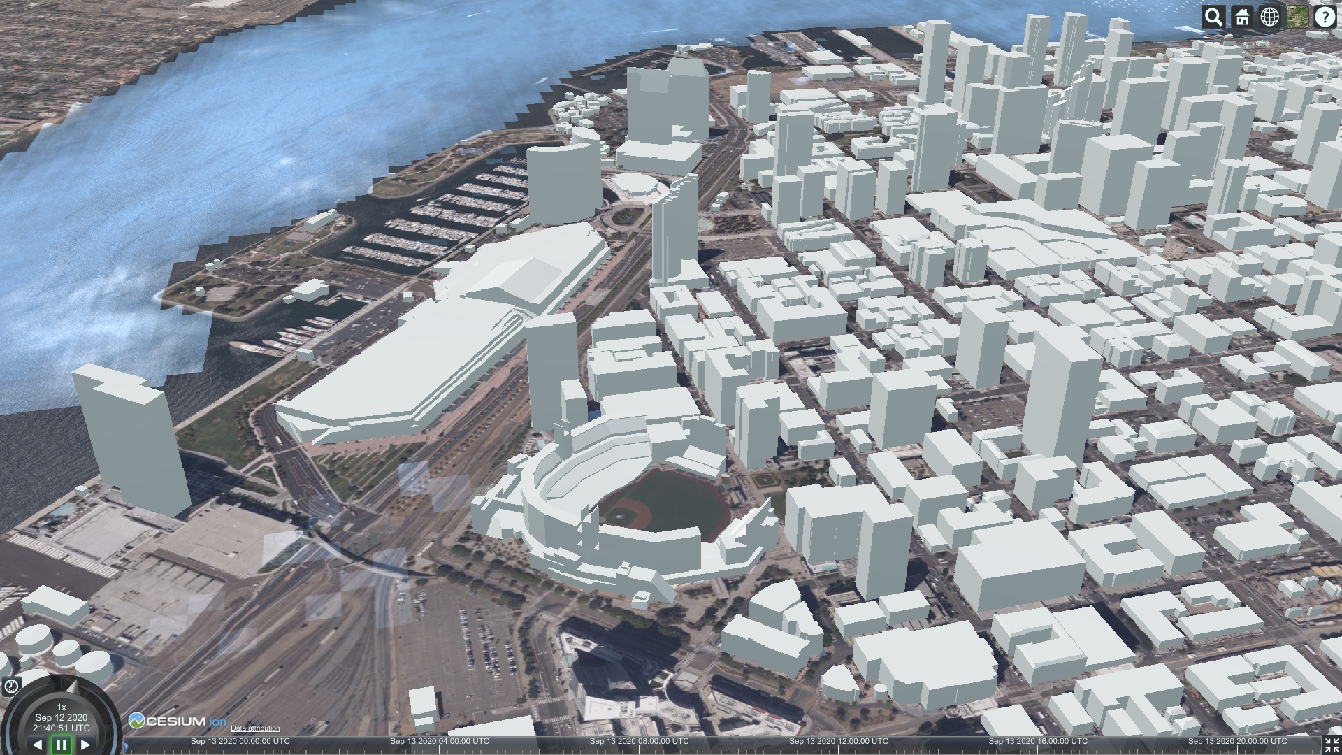
The following screenshots are visualization of the intermediate GNOSIS data store used to generate the CDB X using the same tiling scheme. Part of this effort was accomplished during the OGC Interoperable Simulation and Gaming Sprint. A video was also published.
In addition to the San Diego CDB dataset, worldwide elevation data from Viewfinder Panoramas by Jonathan de Ferranti and imagery from NASA Visible Earth’s Blue Marble are used outside of the extent covered by the San Diego dataset.


This last image features ESA Gaia’s Sky in colour (Gaia Data Processing and Analysis Consortium (DPAC); A. Moitinho / A. F. Silva / M. Barros / C. Barata, University of Lisbon, Portugal; H. Savietto, Fork Research, Portugal.) CC BY SA 3.0.

The following JavaScript code, which can simply be copied to the Cesium Sand Castle, can be used to visualize the data as 3D Tiles, including textures. The code sets up the buildings, trees as well as the Coronado Bridge, together with the Cesium world terrain. One limitation is that the generated tileset is still missing multiple level of details, therefore visualizing a large area will be quite slow.
var worldTerrain = Cesium.createWorldTerrain({ requestWaterMask: true, requestVertexNormals: true });
var viewer = new Cesium.Viewer("cesiumContainer", { terrainProvider: worldTerrain });
var scene = viewer.scene;
var trees = scene.primitives.add(new Cesium.Cesium3DTileset(
   { url: "https://maps.ecere.com/ogcapi/collections/SanDiegoCDB:Trees/3DTiles/tileset.json" }));
var bridge = scene.primitives.add(new Cesium.Cesium3DTileset(
   { url: "https://maps.ecere.com/ogcapi/collections/SanDiegoCDB:CoronadoBridge/3DTiles/tileset.json" }));
var buildings = scene.primitives.add(new Cesium.Cesium3DTileset(
   { url: "https://maps.ecere.com/ogcapi/collections/SanDiegoCDB:Buildings/3DTiles/tileset.json" }));
This 3D Tiles distribution is currently being generated from the GNOSIS Data Store / E3D models. Support to stream as 3D Tiles straight from CDBX GeoPackages should also be achievable.
-
Support for visualizing 3D models directly from the CDB X/GeoPackages dataset in GNOSIS Cartographer client.
-
Support for GNOSIS Map Server streaming 3D models directly from CDB X/GeoPackage.
-
Support for unifying split GeoPackages making up the CDB X dataset as a single data source.
-
Attribution per model within the single tile model. This is supported directly in E3D for triangular face-level attribution (it was clarified that glTF2 does not supports this, and extensions were considering vertex rather than face attributions).
Setup: The data used for these experiments are primarily freely available, and include the following:
-
Blue Marble (NASA) that was georeferenced using GDAL - https://visibleearth.nasa.gov/collection/1484/blue-marble
-
The high resolution inset is from USGS downloads of Central Park in New York City
Tiling Scheme: The tiling scheme uses the GNOSIS Global Grid (using TMS extension — https://gitlab.com/imagemattersllc/ogc-vtp2/-/blob/master/extensions/14-tile-matrix-set.adoc). FlightSafety used the same type of json file {Perhaps a bit moreinfo and a link back?} that Ecere used in their experiment.
LOD Grouping The grouping was pre-set per experiment. The groups were calculated from the highest LOD, back to coarser LODs. For example, if there are 7 LODs (0-6) and a grouping of 4, then LODs 3 through 7 are in one GeoPackage, and LODs 0 through 2 are in another GeoPackage.
Directory and Naming Scheme Each top level tile is within a directory that encodes the LOD, the row (rows are counted from the top, so north to south), and the column (longitude west to east). For example, "L0_R1_C2". Each tile directory contains one GeoPackage file (for example "Imagery_L0_L2_R1_C2.gpkg") and all the tile directories that refine this area (such as "L3_R9_C22"). There were two intentions to this directory structure:
-
Limit the number of files in a directory (to keep from running into OS limitations).
-
Make it a bit easier to export a portion of the world by hand from one CDB X to another.
This experiment was designed to:
-
Show how the top levels of the tiling scheme work,
-
Show the LOD groupings within multiple GeoPackage files, and
-
Show the proposed directory and file naming.
There were eight top level tiles (2 rows and 4 columns) and all GeoPackages that refine one of these tiles are under that tile’s directory structure.
This experiment used the NASA Blue Marble imagery to approximate world-wide imagery at a high level. This provides seven levels of detail of data (L0 to L6). Normally, the GeoPackage files should be larger for efficient use. However to demonstrate the LOD groupings, only four LODs were grouped together. So that tools can view the imagery more easily, the imagery is stored as JPEGs. Originally the thought was to create Jpeg2000 files but checking the results in a tool such as "DB Browser for SQLite" was harder. The content volume for the data used this experiment was around 300 MB.
Compressed 7-zip file with test data can be found at: https://portal.ogc.org/files/?artifact_id=95358
This experiment was designed to further test the limits of the LOD grouping and directory organization. This experiment is similar to the World CDB X Experiment 1 but with a small higher resolution inset of imagery. Images added were 15m data at LOD level 12 covering New York City and 2 ft imagery covering Central Park on Manhattan Island at LOD level 16.
The same processing was used as in Experiment 1 but with an LOD grouping of 6. During the sub-groups planning for this experiment, the hyposthesis was that was an ideal balancing size and number of sub-directories ( (26)2 = 4096 maximum directories within one folder. The maximum LOD for this experiment was 16 (60cm). To find the highest resolution data, look at file CDBX_highres\Imagery\L0_R0_C1\L5_R17_C37\L11_R1120_C2412\Imagery_L11_L16_R1120_C2412.gpkg. The data size for this experiment was almost 1.5 GB.
The full compressed file had to be split into two pieces as a multi-part zip file, to enable saving on the OGC portal.
-
The file names and directory names are pretty hard to read and understand by looking at the files. However, since the tiles are rarely on a "geocell" boundary, a good naming scheme may not exist.
-
Creating the LOD groupings based on the highest LOD of data makes it difficult to add data of a higher resolution later on. This might also make it harder to create "Versions" of the data that have been updated.
-
There were a considerable number of directories created with this tiling and naming scheme. In general, there is a 1-to-1 ratio of files to directories.
These experiments utilized two different tiled layers: Imagery and Elevation. The constraints for this experiment were :
-
There are two different tiled layers: Imagery and Elevation.
-
The data coverage was world-wide, containing 1000m resolution imagery and elevation.
-
The directory structure was reworked to reduce the number of directories produced so that it was no longer a 1-to-1 file to directory ratio. To copy over a section of the world, one would need to copy both the GeoPackage and the directory with similar names
-
The GeoPackage files were renamed to be lod_row_col_endlod.gpkg, to keep the lod/row/column triplet together. For example, Imagery_L4_R9_C6_L6.gpkg
The directory structure was changed from having each GeoPackage within a directory of the same name (yielding a 1:1 ratio of files to directories) to having a finer resolution GeoPackage in a directory with the coarser tile name. If there is even finer/higher resolution data beyond this GeoPackage, that data will be found in a directory at the same level as the GeoPackage with the tile name that matches most of the GeoPackage filename (except for the end lod value). Pictures of the structure below:


This experiment uses the NASA Blue Marble imagery as world-wide imagery and USGS GTOPO30 elevation data. This provides 7 levels of detail of data (L0 to L6). Normally, the GeoPackage files should be larger for efficient use, but to show the LOD groupings, only 3 LODs are grouped together. The imagery is stored as Jpeg, so that SQLite tools can view the imagery easier, and the elevation is stored as 32-bit floating point GeoTiff files. The uncompressed data size for this experiment is around 3.05 GB.
For Experiment 3, the imagery and elevation layers were built into different GeoPackages and different directory structures. For Experiment 4, the imagery and elevation were combined into a single set of GeoPackages and directories while keeping the LOD grouping.
The full compressed files had to be split into multiple pieces as a multi-part zip file, to enable saving on the OGC portal.
-
Experiment 3 compressed zip files containing both data layers as separate GeoPackage layers in the CDB X tiling output:
-
Experiment 4 compressed zip files containing both data layers in a merged GeoPackage layer in the CDB X tiling output
-
The file names and directory names are pretty hard to read and understand by looking at the files. However since the tiles are rarely on a "geocell" boundary, their might not be a good naming scheme.
-
Creating the LOD groupings based on the highest LOD of data makes it difficult to add data of a higher resolution later on. This might also make it harder to create "Versions" of the data that have been updated.
-
There are a lot of directories created with this tiling and naming scheme. In general, there is a 1-to-1 ratio of files to directories, and directories seem to be more work for an OS to create/modify/delete.
-
Current official GeoPackage standards are pretty rigid for raster data. Tiles support a very limited set of raster types (PNG or JPG), and the coverage extension supports only 16-bit PNG or 32-bit float GeoTiff. Current OGC CDB 1.1 supports data types of 8-bit unsigned, 8/16/32 bit signed, and 32-bit floating point data types, with CDB 1.2 adding the capability to support Tiff bilevel images (1-bit).
-
Do we need the extra flexibility of putting different layers in different directory structures (and thus different GeoPackage files)?