Tutorials, code sketches, related media
In this tutorial, I will give a step by step instruction on building the esp circuit, programming it to function through a browser, and finally, programming it to function through an android or ios app.
DISCLAIMER: This tutorial will likely become less and less accurate past June 30/2015, as the esp and its surrounding community is rapidly evolving its capabilities
“The ESP8266 WiFi Module is a self contained SOC with integrated TCP/IP protocol stack that can give any microcontroller access to your WiFi network. The ESP8266 is capable of either hosting an application or offloading all Wi-Fi networking functions from another application processor. Each ESP8266 module comes pre-programmed with an AT command set firmware, meaning, you can simply hook this up to your Arduino device and get about as much WiFi-ability as a WiFi Shield offers (and that’s just out of the box)! The ESP8266 module is an extremely cost effective board with a huge, and ever growing, community.
This module has a powerful enough on-board processing and storage capability that allows it to be integrated with the sensors and other application specific devices through its GPIOs with minimal development up-front and minimal loading during runtime. Its high degree of on-chip integration allows for minimal external circuitry, including the front-end module, is designed to occupy minimal PCB area. The ESP8266 supports APSD for VoIP applications and Bluetooth co-existance interfaces, it contains a self-calibrated RF allowing it to work under all operating conditions, and requires no external RF parts.”
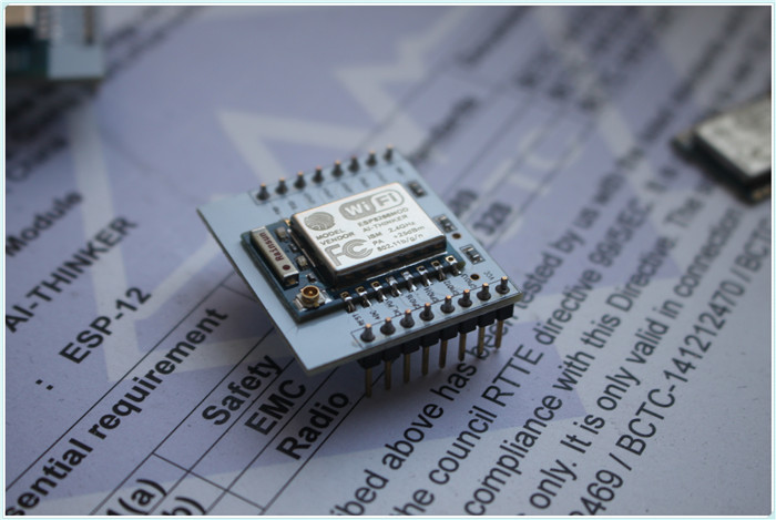
- ESP8266 - 12 + adapter plate expansion
- FTDI basic breakout - 5v OR 3.3v
- MB102 Breadboard Power Supply Module 3.3V 5V For Arduino Solderless Breadboard
- MB102 power cable/wall adapter
- mini-usb cable
- breadboard
- jumper wires (male to male; male to female)
- LED
- 1 x 220 ohm resistor
- 2 x 10k ohm resistor
See https://github.com/esp8266/Arduino for more information
- Solder the ESP chip to the breadboard adapter
- Connect the circuit for bootloading:
| PIN | Resistor | Serial Adapter |
|---|---|---|
| VCC | VCC (3.3V) | |
| GND | GND | |
| TX or GPIO2 | RX | |
| RX | TX | |
| GPIO0 | GND | |
| Reset | RTS* | |
| GPIO15 | PullDown | |
| CH_PD | PullUp | |
| GPIO14 | LED |
The best way to update the firmware of the ESP8266 module is using a Windows PC. IMPORTANT: In order to update your ESP8266 to the latest firmware version available, you need to change your circuit! GPIO 0 must be connected to GND pin.
- Temporarily disconnect the ESP’s VCC from 3.3v
- Connect the FTDI to your computer and allow the driver to install, see details and make a note of the COM port it connects to (this can also be checked through the control panel device manager)
- Plug the MB102 into the wall using an adapter cable and press the power button on that chip
- Click here to download the firmware flasher.
- Unzip that folder
- Open the application in the unzipped file
- Select your COM port
- Press start button (F)
- Wait a minute while the ESP led flashes blue and then you should see a green check icon appear in the bottom left corner.
- Kill the power to the breadboard (power button on the M102)
- Connect the GPIO0 pin to 3.3v and disconnect the VCC
- Install Arduino 1.6.4 from the Arduino website.
- Start Arduino and open the serial monitor, set to ‘Both NL & CR’ with ‘9600 baud’
- Turn the breadboard power back on
- Connect VCC, the ESP should flash blue and you should see some text in the serial monitor
- Type AT in the prompt and the ESP should flash blue and respond with OK if not, repeat from step 1 with a different baud rate (try 115200)
Your esp has successfully connected to the pc!
Starting with 1.6.4, Arduino allows installation of third-party platform packages using Boards Manager.
- Kill the power to the breadboard (power button on the M102)
- Connect the GPIO0 pin to GND
- Start Arduino and open Preferences window.
- Enter http://arduino.esp8266.com/package_esp8266com_index.json into Additional Board Manager URLs field. You can add multiple URLs, separating them with commas.
- Open Boards Manager from Tools > Board menu and install esp8266 platform (and don't forget to select your ESP8266 board from Tools > Board menu after installation, as well as specify the COM port of the ftdi).
- Restart Arduino
- Power on your breadboard
- Under File/Examples/ESP8266mDNS, you will find and open the sketch mDNS_Web_Server
- Configure the ssid and password to match your wireless network, save the file, then upload this to your ESP
- If the console throws an error, try turning off power, shutting down Arduino, disconnecting your FTDI, reconnecting your FTDI, then redoing steps 6 and onward
- go to your http://esp8266.local/ URL and write down the ip address.
You have successfully configured your esp to communicate through a browser!
- Under File/Examples/ESP8266WiFi, you will find and open the sketch WiFiWebSever
- Replace ‘server_ip’ in http://server_ip/gpio/ with the ip address noted in the previous section
- Configure the ssid and password to match your wireless network, save the file, then upload this to your ESP
- If the console throws an error, try turning off power, restarting Arduino, disconnecting your FTDI, reconnecting your FTDI, then redoing step 3
- http://server_ip/gpio/1 will turn ON the LED connected to GPIO2, whereas http://server_ip/gpio/0 will turn OFF the LED
- Install the Blynk app from your app store on your mobile device (you must create an account to use it for free)
- Create a project using the app UI which toggles gpio2 between LOW and HIGH
- In project settings (leftmost button in the upper right corner), set your hardware to esp8266 and email yourself the AUTH TOKEN
- On your pc, install this Blynk library for the Arduino IDE
- If the console throws a very long error, you might have installed the wrong library, check here for more information and scroll down to the end to see the latest posts
- Restart Arduino
- Under File/Examples/Blynk/BoardsAndShields, you will find and open and sketch named ESP8266_Standalone
- In the sketch, set char auth[] = (the auth token you just emailed to yourself via the app), as well as set your ssid and password in the setup() function.
- Save the file, then upload this to your ESP
- if the console throws an error, try turning off power, restarting Arduino, disconnecting your FTDI, reconnecting your FTDI, then redoing step 8
- Once it is done uploading, on your mobile device, press the play triangle in the top right corner of the app. You should now be able to turn the LED on or off using your device!
ESPxx Hardware
| PIN | Resistor | Power supply |
|---|---|---|
| VCC | VCC (3.3V) | |
| GND | GND | |
| GPIO0 | PullUp | |
| GPIO15 | PullDown | |
| CH_PD | PullUp |
ESP community forums: http://www.esp8266.com/viewforum.php?f=4
pastorhudson esp + ftdi + arduino ide: https://www.youtube.com/watch?v=-aZU8YqHlHw
Ruis Santos ESP tutorials: https://www.youtube.com/playlist?list=PLeJ_Vi9u6KisKTSNeRRfqsASNZdHSbo8E