wireing diagram
This wire diagram shows the complete wireing of the minimOSD and the rx5808.
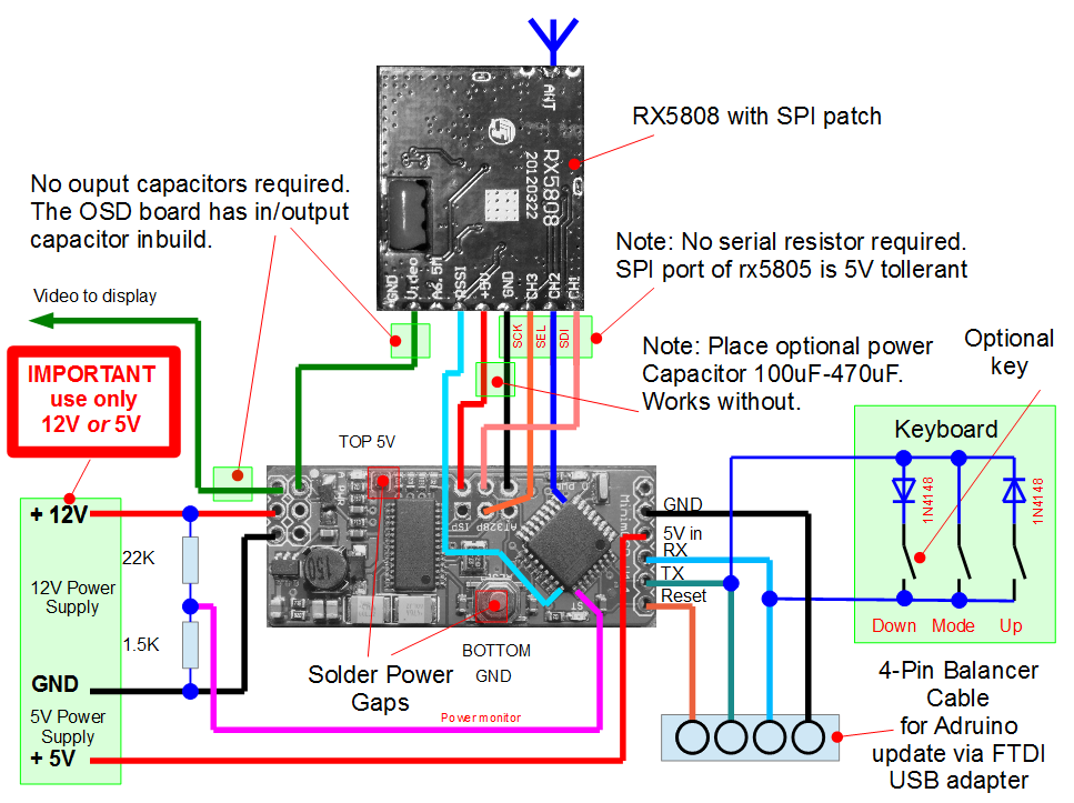
The power supply of the OSD chip and the Arduino will come from ONE 5V supply. Therefore the two solder jumper on top and bottom must be soldered.
The system can be powered from 5V on the right side OR from 8-12V on the left side.
YOU MUST USE ONLY ONE SUPPLY AT A TIME. MAKE YOUR CHOICE DEPENDING OF YOU APPLICATION (5V or 12V).
The switching power supply on the minimOSD has enough power to source up to 400mA. This means it can power the rx5808 without any problems (needs 100mA according data sheet).
The power monitor with the resistor divider is optional.
The SPI bus is 5V tolerant, so the SPI can be connected directly to the Arduino.
On the video there are NO exernal capacitors required, since they are already on the minimOSD board.
The keyboard uses just 2 wires for 3 keys. This is possible by adding diodes and a software driver that "tries" all directions. This is simple to wire, but only one key at a time can be detected.
For minimum operation, the MODE and UP key is required.
As you see, is the keyboard connected to the RX and TX of the Adruino UART. This works since the ports can be used as GPIO.
IMPORTANT: Do not press any key during firmware update, since the RX/TX data gets corrupted. In case you ignored this by accident, simply disconnect your FTDI adapter and programm again.
As update connector I added just a 4-pin connector. I used a 2.54mm connector (e.g. old 3S balance cable).
This must be connected to an USB FTDI Adatper. Make sure the Reset pin is driven to the DTE of the FTDI adapter. Otherwise the Arduino GUI can not reset the board and therfore can not talk to the bootloader.
**NOTE: Cheap china minimOSD board may not have an Arduino Bootloader. This must be programmed with an ISP programmer accoring to the Arduino manuals. It is recommended to programm this before soldering wires to the ISP connector to make live easier. It works just to "insert and bend" a 6 pin 2x3 connector without solder. **
This is the most difficult task. You should have some solder experience or you will kill the board with shorts.
I found this video showing a good method how to solder in a good manner.
YouTube video of patching minimOSD
You must at least solder the SEL for the rx5808 (blue wire in diagram) and the RSSI signal (turkis wire).
The power monitor is optinal, but helpfull.