This repository contains the design files for my VPForce DIY Force Feedback Kit modification of the Virpil ACE pedals.

The build can be completed without making any permanent modifications to the pedals. There are 3x M6 holes in the main pulley and pulley mounting plate that can be used to secure the center of the plate to the upper arm if you so desire, but that will require drilling 3x 6mm holes in the upper arm of the pedals. These bolts are not required and , to date, I have not installed them on my build.
Sept 9, 2023
- Added updated control mount STL file that mirrors the key/notch for the potentiometer orientation
- Added updated main pulley mounting plate which has a recess to account for variences in the pedal manufacturing where the main center axis bolt head can protrude above the pedal arms
- Corrected the hardware in the build sheet for attaching the main pedal assembly to the 2040 rails from m5x25 to m5x20
The Virpil ACE pedals 3D model that is part of these design files is of my own making. It was not provided by, nor does it have any affiliation with Virpil. The only truly accurate aspects of the model are the 130x135mm bolt pattern of the base and the M6 mounting hole locations where the gear mount attaches to the upper pedal arms. The remainder of the parts are drawn by me using rough measurements and eye-balling.
Any potential long term affects of the lateral forces being applied to the bearings of the Virpil pedals are unknown.
Modify your pedals at your own risk
- Virpil Ace Pedals
- VPForce 86BLF03 single motor kit
- Various Aluminum Extrusion sizes and lengths
- Assorted T-slot hardware (t-nuts, angle brackets, join plates)
- Various 3D printed parts
- A suitable timing belt
- A suitable drive pulley
- Assorted wire for power plug and shutoff switch / potentiometer (~14-16AWG for power and ~22AWG for pot)
- JST-HX connector and crimping tools for potentiometer->control board connection. You can also find long pre-terminated pigtails on amazon. The pigtail that comes pre-attached to most Pots is not long enough.
A full as-built build list is provided in the repository:
** Updated Sept,9 2023

The above list covers the majority of what you will need to build this project. Other things you will probably need include but are not necessarily limited to:
- Ability to cut the aluminum extrusion
- A miter saw with an aluminum/non-ferrous metal cutting blade works well
- Ability to solder and/or the tools necessary for crimping JST plugs
- Various tools necessary for construction (Alan wrenches, etc)
- M6 Tap set required to thread the end-holes of the 2080 extrusion for the motor mount
The following is a mostly unstructured brain dump for the build where I think things may require some explanation.
For the most part, it should be apparent in the assembly STEP file how things go together but there are a few things might not make sense at first glance. Hopefully I can cover those in the ramblings below.
-
The design as built is using a 6:1 gear ratio, with a 15 tooth drive pulley and a 90 tooth main pulley. With the 86BLF-03 motor kit from VPForce, I am able to achieve greater resistance at %60 spring force (in the configuration software) than the Virpil pedals can provide with the heaviest springs installed.
- Because of the way the Virpil base attaches to the 2040 rails, it would be easy to experiment with different gear ratios and belt lengths.
- It may also be possible to use the stronger 86BLF-04 motor, but you may need to move the frame cross brace that sits below the motor (due to the extended motor length). However, as previously stated, the '03' motor provides ample forces.
-
The arms that hold the springs on the pedals also serve as a throw limiter. If you remove the arms (to stop them flopping around with no springs installed), the end-to-end throw of the pedals will increase significantly and be far too much.
- There are printable throw limiters in the project files and a picture in the photos folder which shows where/how they are installed. The notch in the limiters is to aid in installation and should face outwards when installed. I recommend you print them at %100 infill.
-
The control box is designed to be a tight fit for the control board and wiring. You will likely need to shorten the pigtail that comes attached to the USB connector in the VPForce kit in order to get it all to fit in the enclosure.
- The 3D printed cable grommets are not the best design, and aren't strictly required. They are a pain to get in place with the wiring while you are attaching the back plate, but they do help keep things nice and tidy.
-
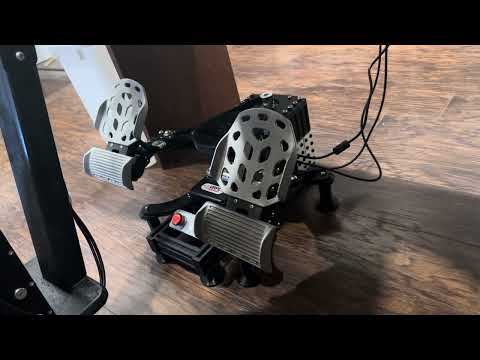
If you have hard flooring and are looking for a way to secure the pedals, I cant speak highly enough of the Airstick micro-suction 'tape' from Sewell (https://sewelldirect.com/products/airstick-microsuction-tape). I have hardwood in my office and a small square of this under each foot keeps the pedals firmly in place, yet it is possible to pry them up for cleaning and then re-stick to the floor. You can generally find small quantities for sale on their site or on Amazon.