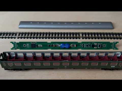
My Homebrew D13 LED decoder is a drop in design for Minitrix (#15791) coach with no mechanical modification required. The decoder is designed to integrate into the RTB digital control infrastructure.
Current status:
See also
- RTB_D12 - custom (Fleischmann V100)
- RTB_D16 - NEM651
- RTB_D20 - NEM651
- RTB_D21 - Next18
- RTB_D22 - Plux16
- RTB_D23 - NEM652
User Guides
- User Guide - DE
- User Guide - EN

- DCC
- DCC-A automatic logon
- DCC-R protocol extension
- Service Mode Programming
- Railcom
- Channel 1/2
- POM, xPOM
- DYN: QoS, Track-Voltage, Scap-Voltage, Temp, Ambient light
- 1x4F/2.8V SCAP (on PCB)
- Inrush limited
- step up/down converter
- max track voltage 25V
- Corridor (11 LEDs), Cabin (13 LEDs), Lavatory (2 LEDs)
- Status LEDs: heartbeat, charging, no-power
- motion sensor
- ambient light sensor
- fast firmware update within seconds on main tracks via DCC-R
The current PCB layout uses SMD footprints with 0.5mm pitch and mainly 0603 parts. Reflow soldering is recommended whereas handsoldering will be difficult.
- 4-layer PCB, FR4, 1mm
- CPU: AVR64DA48


Filename structure: { pcb }{ code }{ version }.hex
Example: D13F0001.hex
| Description | |
|---|---|
| pcb | Name of matching hardware (D13) |
| code | Type of code contained (R=rom, B=bootloader, F=flash, U=bld update, P=UPDI factory code) |
| version | Release version (####) |


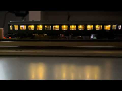
See the D13 decoder in action.

This project is intended for hobby use only and is distributed in accordance with the Apache License 2.0 agreement.