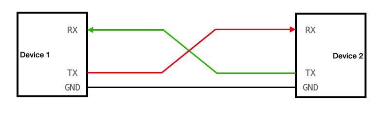
UART stands for universal asynchronous receiver / transmitter and defines a protocol, or set of rules, for exchanging serial data between two devices. UART is very simple and only uses two wires between transmitter and receiver to transmit and receive in both directions. Both ends also have a ground connection. Communication in UART can be simplex (data is sent in one direction only), half-duplex (each side speaks but only one at a time).
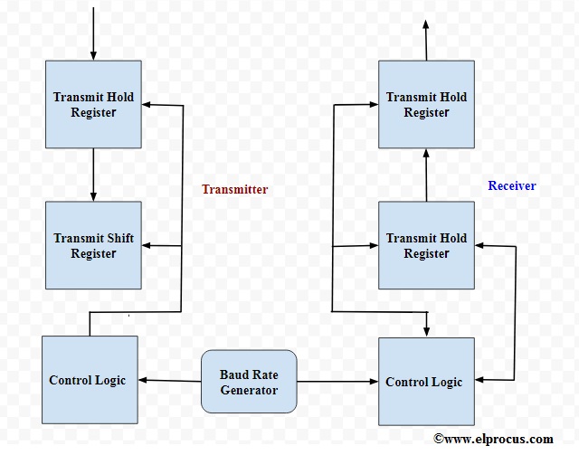
The Verilog implementation of an 8-bit and 32-bit UART features a RTL design. The architecture is structured around four key modules: the Baud Rate Generator, Transmitter (TX), Receiver (RX), and the UART's top-level module, which functions as the Register Interface (RIF) unit.
In the architecture, the Baud Rate Generator serves as the arbiter of data transfer speed, determining the rate at which information is transmitted from the transmitter to the receiver, quantified in bits per second or signal units per second. The magnitude of the baud rate directly influences the volume of data that can be efficiently transferred within a given timeframe.
The Transmitter and Receiver modules intricately manage the bidirectional flow of data, overseeing the transmission and reception of information, respectively. At the apex of the hierarchy, the UART module assumes a central role, skillfully orchestrating these modules. It functions as the Register Interface, fostering the seamless exchange of data between the internal registers of the UART and external components.
This architectural design harmoniously encapsulates the specialized functionalities of each module, fostering the effortless transmission and reception of data. Simultaneously, it meticulously crafts a structured and organized interface, enhancing the efficiency of data exchange between the UART and external systems.
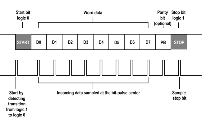
UART, or Universal Asynchronous Receiver/Transmitter, employs a packetized mode of transmission. The intermediary link between the sender and receiver involves the generation of serial packets and management of the associated hardware lines. These packets comprise a start bit, data frame, parity bit, and stop bits.
This repository also includes a simulation testbench (UART_8bit_tb.v) to assist you in verifying the functionality of the UART module. You can use this testbench with Verilog simulation tools like GTKWave to observe the module's operation.
Ensure you have a Verilog simulation tool installed.
Compile the UART_8bit.v and UART_8bit_tb.v files.
Run the simulation, and monitor the waveforms to observe the UART module's behavior.
Clone the project
git clone https://github.com/ZAIN-ALI-02/UARTGo to the project directory
cd UARTInstall dependencies
  install vscode
  install GTKWave
install icarus verilogTo run tests, run the following command
  iverilog -o UART_tb_8bit.vvp UART_tb_8bit.v
  vvp UART_tb_8bit.vvp
GTKWave UART_tb_8bit.vcdContributions are always welcome, suggestions, and issue reports. Feel free to create pull requests or open issues to help improve this UART implementation. Together, we can make it even better!
This project is open-source and available under the MIT License. You are free to use, modify, and distribute this code as long as you comply with the terms of the license.