The understanding of how wiring the RGB LED into a breadboard works since (from my experience) Arduino doesn't do the best job introducing beginners. The code provided was based off of the code of Matthew L Beckler with small details by me for extra clarification
Analog inputs for common cathodes and anodes are both values between 0 and 255 and voltages of 0v to 5v
-
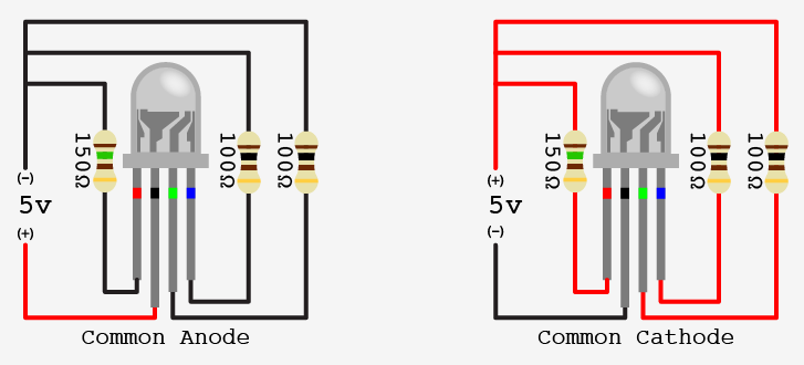
*The longest pin on a common anode RGB LED should be connected to 5v pin on the Arduino
-
The other 3 pins (R, G, and B) should be connected to 200 ohm resistors in series
while(Serial.available()==0){
   }
   blueBrightness = 255 - Serial.parseInt();
/**
    Here, the value is taken and the difference between value and 255(peak value) is stored in the variable.
**/

   Serial.println(blueBrightness);    //Prints value on the serial monitor
   Serial.println("   ");
analogWrite(blue, blueBrightness);    //sends analog signals to blue LED
-
The longest pin on a common cathode RGB LED leads to the GND pin on the Arduino
-
The other 3 pins (R, G, and B) should be connected to 200 ohm resistors in series (same as the anode)
while(Serial.available()==0){
  }
  redBrightness = Serial.parseInt(); //Stores value in variable
  Serial.println(redBrightness);    //prints value on serial monitor
analogWrite(red, redBrightness);     //sends analog signals to red LED
credit to Hackster.io for the idea and the sample code in the interpretation portion