-
Notifications
You must be signed in to change notification settings - Fork 639
New issue
Have a question about this project? Sign up for a free GitHub account to open an issue and contact its maintainers and the community.
By clicking “Sign up for GitHub”, you agree to our terms of service and privacy statement. We’ll occasionally send you account related emails.
Already on GitHub? Sign in to your account
"New" Magic Home LED Controller has incorrect RGB channel configuration #475
Comments
|
Support to change channel configuration from the web UI is scheduled for milestone 2.0. Your board is a 3 channel board so based on your findings I would say the configuration should be: Just replace the "Light" section under MAGICHOME_LED_CONTROLLER definition in hardware.h with these settings, rebuild and flash. |
|
xoseperez could you explain this in more detail? im a noobie and have this issue <3 |
|
The Now, with 2.0 the idea is to be able to configure this via the web UI so there will be maybe a few different generic devices and a configuration file for each independent model, plus the option ot manually change the configuration via the web ui. |
|
@BakaOsaka Did you test the configuration I sent with this board? |
|
My red and green channel are inversed. How would I change that? |
|
Never mind. I swapped the LED pins in hardware.h and build the firmware myself. :) |
|
I have the feeling there are a few different configurations out there... the only way to really fix this is to have a generic multichannel dimmer image where you can configure the number of channels and the GPIOs they are on. |
|
I also bought some magichome controllers, from aliexpress. Link: https://www.aliexpress.com/item/32847409018.html They look different from below, especially different from the one shown in the wiki and have the following pin layout: |
|
@l3d00m Yep, same thing here. Yesterday I received new devices and those look exactly the same as ones on your pictures (board marked as "ZJ-WFMN-A V1.1" on WiFi PCB antenna). For those boards you can use firmware for ARILUX_AL_LC02_V14 (for example espurna-1.13.5-arilux-al-lc02-v14.bin) - same pinout. I've added information about it to the wiki. |
|
Oh I see, they are already in the wiki under https://github.com/xoseperez/espurna/wiki/Hardware-Arilux-AL-LCxx. Didn't expect that, but added a link to the article from the normal MagicHome wiki because otherwise some people wouldn't find it I guess. Thanks for the info :) |


Hi,
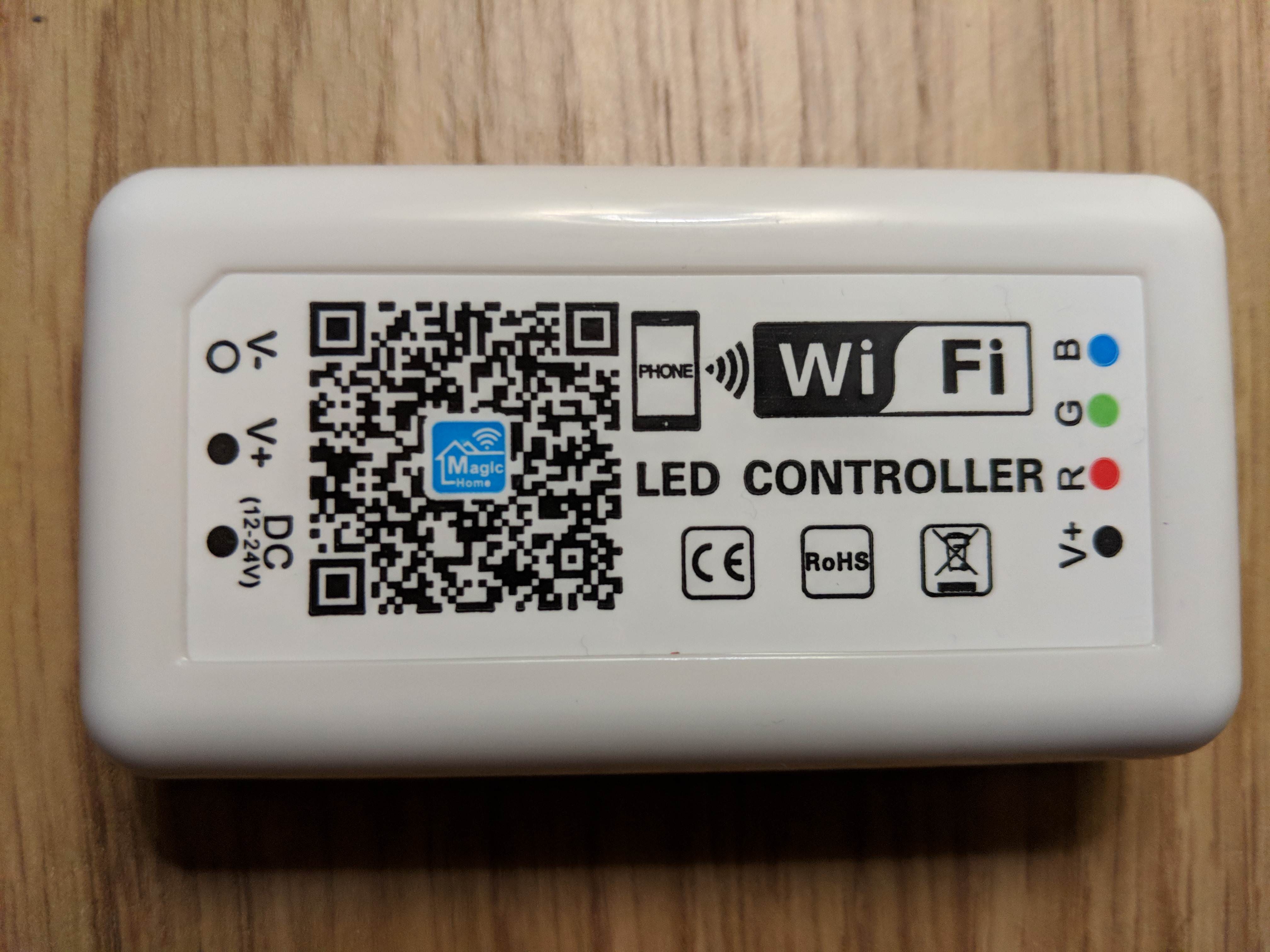
Today I recieved a Magic Home LED Controller that I ordered from here.
(I am assuming this is the same brand of Magic Home LED Controller specified on the Wiki, however the brand for this one claims to be Boledengye instead of Sagelumei)
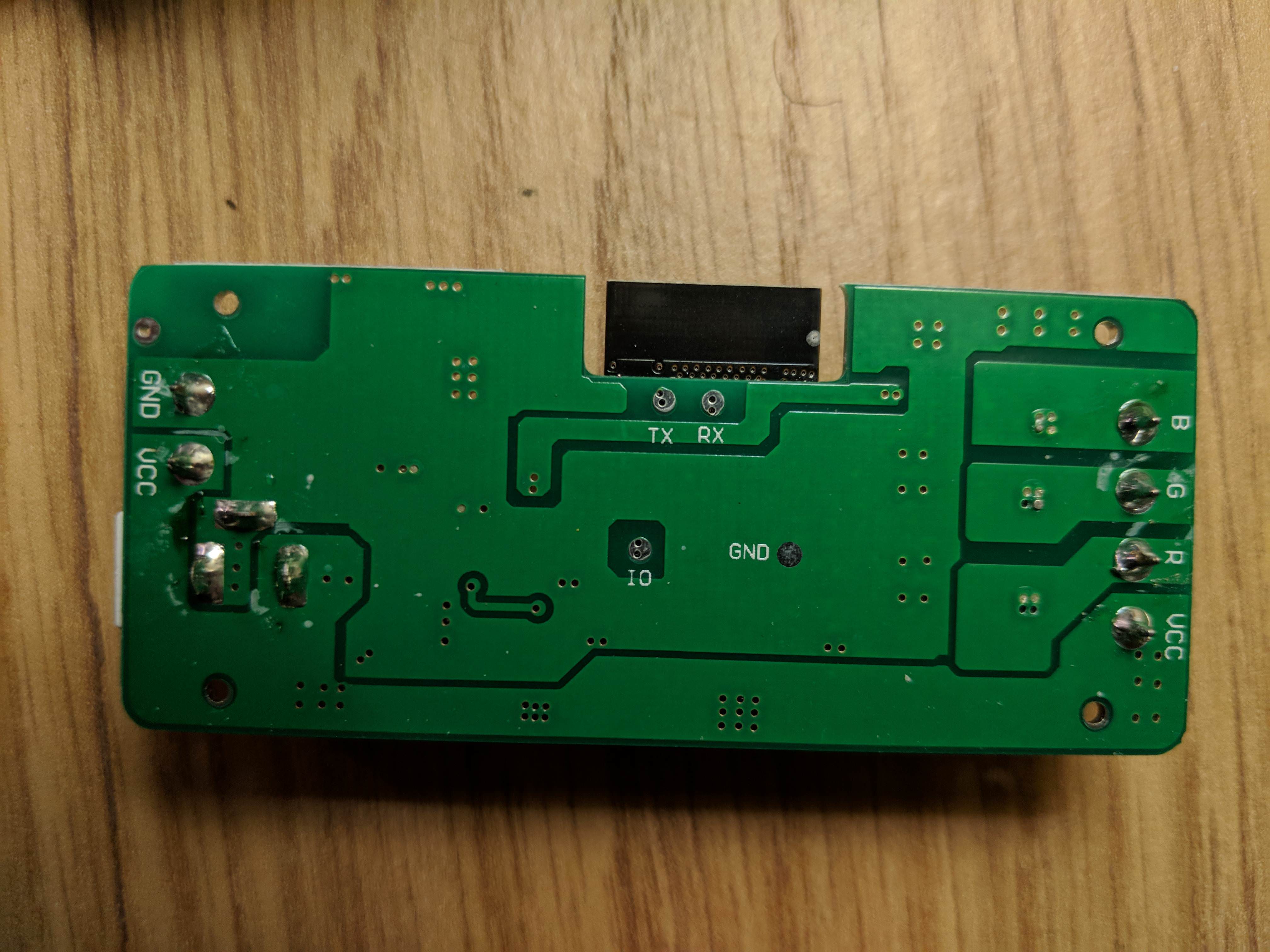
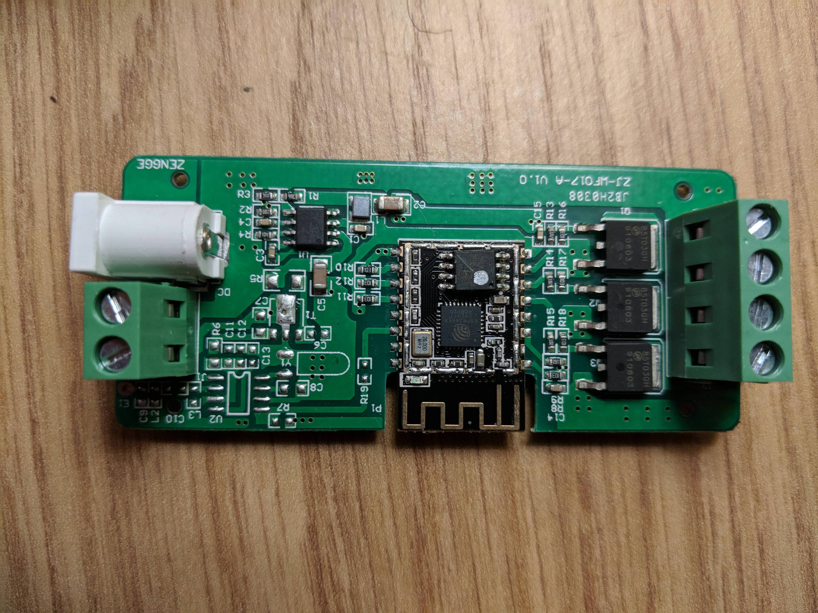
Upon opening it to flash ESPurna, I noticed the board layout was different from that shown on the Wiki:


I was, however, able to successfully flash the firmware using the visible RX/TX/GND and shorting the IO point.
I initially flashed the "Magic Home LED Controller 2.0" firmware, as I believed this board was just that revision (which is not pictured on the Wiki). However, only the Red and Green channels were available, and the RGB Picker was not reflecting the true state of the colours.
I subsequently flashed the "Magic Home LED Controller" firmware, and now all the LEDs are accessible, albeit incorrectly:
This means the RGB picker will still not work, and I can only manually specify the colours using each channel.
If this is an ongoing issue (Multiple revisions with slight changes) would it be possible to add support to manually specify the channels from the web interface? That way, it would be possible to reconfigure the existing channels so that they would work with the RGB picker.
The text was updated successfully, but these errors were encountered: