Soroka v2 Build Guide [EN]
Any translation help would be appreciated
- A soldering iron with temperature control and a thin cone tip
An example of a suitable soldering tip for installing inserts:

- Two thin metal tweezers, one of them can be replaced with any jumper
- Flux for soldering and solder
- Copper braid for removing solder (in case of problems with soldering, optional)
- desoldering pump (optional)
- Screwdriver or hexagon
- Superglue
- Toothpick or match
- Isopropyl alcohol or Flux-OFF
- Wipes or rag to clean excess flux
- Soroka v2 PCB, 1 pc
- Soroka v2 Plate, 1 pc
- Soroka v2 Case, 1 pc
- Soroka Spacer, 1 pc
- Diodes 1N4148W, SOD-123, 51 pcs
- RP-2040 Zero, 1 pc
- Fused inserts M2, 13 pcs- M2 screws, 4 mm, 13 pcs
- Oval legs 22x4x1.5mm, 4 pcs
- Silicone washers 5 x 2 x 1, 9 pcs
- Neodymium magnets 3mm x 1mm, 8 pcs
- Panasonic EVQWGD001 or 12.5 mm EC11 encoder (Optional), 1 pc
1. Check the functionality of the controller. To do this, connect the controller to the computer using a USB cable, the LED on it will start flashing. Then you need to hold down the BOOT button and at the same time click RESET. The computer should detect the new device and open the drive folder. You can immediately upload the firmware file in .uf2 format by simply dragging the file to a folder. After copying the file, the drive should automatically reboot and exit firmware mode.
2. Install diodes.
It is necessary to apply a flux on the landing pads of the diodes. Better to go through the rows one by one. Apply the flux to one row, solder the diodes, and then repeat 3 more times. Diodes have a polarity, so it is important to place them on the right side. There is a cathode mark on the diode (a light strip on the body, on the side of one of the terminals), it must be positioned on the closed side of the white rectangle on the board. An example in the photo:
3. Install the controller.
The controller must be positioned on the same side as the diodes. The controller buttons should be inside the cutout on the board and look at the front (upper) surface of the board.

For smooth and easy installation, use pins. Before placing the controller, it is necessary to apply the flux to the pads on the board and the controller.
IMPORTANT NOTE! The pins are used ONLY for alignment, they DO NOT NEED to be soldered.
I install the pins on the bottom and left side and solder the pads on the remaining one. After that, I take out the pins and solder the rest of the controller pads.

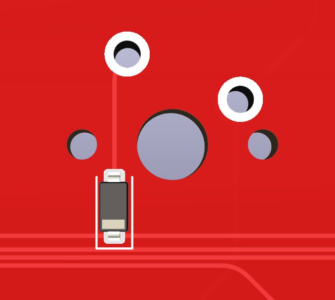
4. Install the encoder and solder the encoder.
In the case of a Panasonic encoder, it is necessary to "hook" it to the board, and then solder all the pins.
A "hook" that must be hooked onto the board

5. Wash off all flux stains from the board. Apply alcohol or cleaner and remove everything with a dry cloth or napkin. In some cases, you can brush off heavy stains with a toothbrush.
6. Check the PCB after soldering. After the board dries, connect the USB cable. If you didn't upload firmware yet, see step 1. The verification:
-
Launch the VIAL- Go to the Layout tab and set all the desired options
-
Go to the Matrix tester tab and click on the Unlock button
-
Use two tweezers to connect the pins of the first two switches in the first row and wait for the unlock progress bar to fill up.
-
Using tweezers, close the contact pads of all switches. This will make sure that soldering is done without any mistakes.
-
If individual buttons do not work, it is necessary to check the soldering of the corresponding diodes, if the whole row or column does not work, it is necessary to check the soldering of the controller pads. 7. Install the switches in the plate (optional) and solder the switches with the desired layout. Carefully remove excess flux, if any.


8. Congratulations, you are amazing!
0. Install silicone feet on the bottom of the case

1. Melt the inserts into the seats inside the case. To do this, install the insert into the mounting hole of the case, and with a heated soldering iron, slowly lower it down. IMPORTANT! The soldering iron must be held perpendicular to the plane of the inner bottom. No need to put extra effort into it. If the insert is hard to enter, increase the temperature slightly or wait until all the parts are sufficiently heated._
2. Melt the inserts into the spacer under the panel. The inserts are located closer to the edges, the holes under them are deeper. Here's the right side:

3. Glue the magnets into the spacer. I recommend doing everything one at a time, so as not to get confused with the polarity of the magnets, otherwise it will be impossible to get them, the part will be damaged. Places to install magnets:

The sequence is as follows:
- Squeeze a drop of superglue onto a piece of paper or thick cardboard
- Use a toothpick to apply a little glue into the magnet hole
- Install the magnet and remove excess glue
- Repeat this operation for all spacer magnets.
4. Glue the magnets to the lid. It is very important to glue the side. The sequence of actions:
- Place the magnets on the already glued spacer magnets. This will allow you to find out the polarity and which side will need to be glued.
- To eliminate errors, you can put dots with a marker on the visible surface of the magnet. This will be the side that will be placed inside the lid.
- Glue the magnets alternately, as was done for the spacer. A dot from the marker INSIDE the lid.
5. Screw the spacer to the PCB with screws. The location of the screws for the spacer:

6. Install silicone washers inside the housing seats Places where silicone washers are installed:

7. Install the finished PCB inside the case by screwing in the screws.
8. Install a magnetic lid and keycaps